Wednesday, May 28, 2008

Servo Wiring

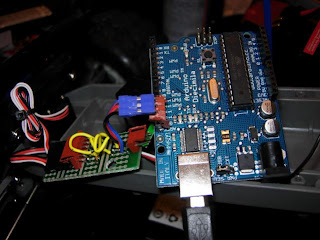
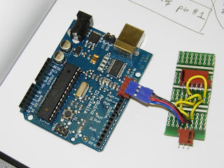
Connecting the Arduino board to the forward servo and the ESC requires an adapter board. Marcel and Ash from the robotics team sketched out the wiring and soldered it for me, as that's a skill I've yet to pick up. Here's a pic:

Arduino and the adapter board.

Sometimes I'll refer to the ESC as a servo, as that's how it needs to be treated electronically. The adapter serves three purposes:
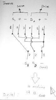
  1. Connects the signal wires from each servo to digital output pins on the Arduino.
  2. Connects the Arduino's ground pin to both servo ground wires. The ground must be common, or none of the signalling will work.
  3. Connects the steering servo's 6V supply to the ESC's 6V line, to provide power. This doesn't connect to the Arduino at all.
Here's the wiring diagram:

Adapter board wiring.

S1 and S2 are the signal lines, going to digital pins 12 and 13 on the Arduino, respectively. Digital pin 13 also happens to control the built-in LED indicator, which flickers now when that signal is sent. The ground is common, of course. The servo lines therefore plug directly into the adapter board, so it can replace the radio receiver.

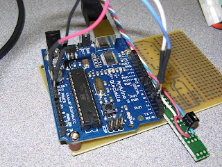
Everything all connected.

Using the Servo.h library for Arduino, it's relatively easy to control the steering servo: you specify a position between 0 and 180 degrees, and call refresh at least once every 20ms, and the servo will move. The servo doesn't need its full range of motion, as the steering links don't have that much travel. Moving the servo between 40 and 140 degrees is enough to fully articulate the steering: any more and you can hear the servo grinding and the servo saver stressing.
Unfortunately the ESC is another story. So far no signal I've sent it has elicited any response. I'll have to find some documentation on how that one works.

The servo code is based on the tutorial on the Arduino Playground. Here it is:

#include
#define pin1 12
#define pin2 13

Servo servo1;
Servo servo2;

int angle = 90;
int dir = 1;
int counter = 0;
int counterMax = 100;

void setup()
{
servo1.attach(pin2);
Serial.begin(9600);
Serial.print("Ready");
}

void loop()
{
static int v = 0;

if(counter > counterMax)
{
counter = 0;

angle = angle + dir;
if(angle > 140){dir = -1;}
if(angle < dir =" 1;} servo1.write(angle);

Serial.print("angle: ");
Serial.println(angle);
}
counter++;

Servo::refresh();
}

Note that you need to download the Servo.h code, which is available through the tutorial linked earlier. Anyway, here's a video of the Arduino running the steering:
Sunday, May 25, 2008

Electrical Anatomy of the Stampede

The first thing was to partially disassemble the Stampede and work out how the pieces go together. I'm not planning any major changes to the chassis mechanics. Most R/C modifications are for better speed and performance, which is not the intention here. The chassis is a rectangular plastic tub with shock towers at each end.

Stampede chassis with wheels removed.

Only the rear wheels are powered, and the steering is controlled by a single servo, visible as a black box between the two front shock absorbers. The shocks attach to the black shock tower, which sports two body mount posts above it. The battery normally lies in the well in the chassis center, and connects to the yellow Electronic Speed Control (ESC). You can also see the blue aftermarket bumper (by RPM Racing) that will protect the front suspension from damage (and hopefully prevent a repeat of the broken caster block).

Front Assembly with steering servo (left under shock tower) and radio receiver (right).

Sorry for the slightly blurry picture. The radio receiver has two channels, channel 1 in the bottom slot controls the steering. A servo has a three-wire interface. The black is the ground wire, the red is the 6V power, and the white is the signal line. The receiver gets its power from the ESC, and returns a signal back to the ESC (channel 2) on the white wire, treating it as a servo. The ESC interprets that signal to control the main motor. The steering servo on channel 1 receives its power from the radio receiver, as well as a signal on the white wire.

If I'm going to replace the receiver with the microcontroller, the steering servo still requires a power supply from the ESC. So, the microcontroller must only send a signal on the white wires, and must be connected into the black ground wire. The red power wire must bypass the microcontroller and remain connected to the servo.

The Electronic Speed Control (ESC)

The ESC receives power from the battery (far left) and passes power to the motor. These wires are heavy-gauge to accommodate the high current passing to the main motor. The thinner three-strand wire at the bottom of the image goes to the receiver, powering the receiver and the steering servo, and receiving back a signal on the white wire, as noted previously.

The main drive motor.

The main motor itself is a Titan 550 12-turn. There's not much need for modifications here: except perhaps to gear the system down. The truck's really fast: far too fast for an autonomous system.

Friday, May 16, 2008

Arduino Diecimila


My very own Arduino Diecimila microcontroller arrived today. The Arduino implements the "wiring" communications library and is open-source to boot. It can serve as the robot's brain, but is limited to simple analog or digital inputs, so vision is right out. It also has a USB-b connector, so it can communicate with a larger computer and can thus serve as a simple chassis interface.

Traxxas Stampede


So there it is: a Traxxas Stampede. It's so much fun to drive around I'm rather reluctant to tear it apart. I'll have to take some care to retain the ability to run it as an R/C car.

The stampede is a 2WD Monster truck. It has a single servo for steering and is capable of 30 mph. I'll reduce the gearing so that it has more torque and a lower top speed for safety.

If you look carefully you can see that the front-right tire is askew. That's because I ran it into a curb and broke the front right caster block. It's currently awaiting a new caster block so it'll run again.

Thursday, May 15, 2008

The Plan

The robot will have the following:
  • An off-road capable R/C chassis in 1/10 scale (good brand names I know: Tamiya and Traxxas)
  • A microcontroller to interface with the chassis electronics and perhaps some of the simpler onboard sensors. (I have a small amount of experience with the Arduino board which makes it my first choice.)
  • An onboard computer for the AI and Vision processing. Right now the leading candidate is the Asus eee PC, but the HP 2133 Mini-Note and various Mini-ITX computers are all in the running. More on this debate later.
  • Camera(s) for vision. Stereo would be great, but that requires two cameras rigidly fixed to one another. I also have to consider the limitations of the computer's USB or Firewire Bus and processor to handle that much incoming camera data at once.
  • Other sensors. Candidates are Ultrasonic Rangefinders, Bump sensors, and Infrared Rangefinders.
  • Power will be supplied by the chassis battery and a additional battery for the computer. Laptops are the most convenient in that regard.
The main task I want the robot to perform initially is roaming with obstacle avoidance, and mapping. Basically the robot should accumulate a map of its surroundings by wandering around and observing them, while keeping track of its own position relative to previously-viewed landmarks. Formally, this is called Simultaneous Localisation And Mapping, or SLAM. Once that's working, who knows what I'll program it to do.

For a software structure the plan is to use Player/Stage with Gazebo, which is an open-source framework for developing robots.

Big plans. We'll see where they go.

The History

This entire project started as a result of participating in the Waterloo Robot Racing competition representing the University of British Columbia as part of the Thunderbird Robotics Team. The challenge was to build a small autonomous robot that could navigate a course demarcated by orange traffic cones. Our entry was based on a Tamiya remote-control Hummer kit, and was controlled by an Arduino microcontroller. The robot had infrared line-following sensors and ultrasonic rangefinders. What the robot really needed was a vision system. I was so enthused by the whole project that I decided that I wanted to build a robot of my own, based on an R/C car.

Wednesday, May 14, 2008

Inception

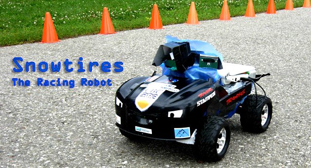
Welcome to the Snowtires Blog, my personal chronicle of the process of building a vision guided robot. This will be my first foray into electronics building and robot construction, so who knows where it will end up. Bear with me and I hope there will be some interesting times ahead.

-tetracanth